Simulation And Critical Evaluation Of Communications Networks
Introduction: Simulation And Critical Evaluation Of Communications Networks
Link to Native Assignment Help's comprehensive assignment help offerings from a trusted UK-based company.
The report is about the digital network communication analysis with a proper diagram. The main aim is to find out the simulation process and simulate the aspects of digital network communication. The processing part can be done and executed using a CISCO packet tracer and the simulation can give the brief execution of network communication analysis. Here, in this analysis, eight different scenarios can be developed. These scenarios are different with each purpose and attribute. Proper PCs, four routers, switches, and other components can be taken as required and the simulation message-sending method can be executed through this. A critical evaluation can also be done in this simulation work.
Description of eight scenarios
This section is about a brief description of the scenarios used in this network communication analysis. Some similar topic areas are selected for the scenarios as can be demonstrated through CISCO Packet Tracer. One of the best scenarios has been taken for the analysis of this digital network communication (Han, and Chen, 2018). The large distribution of the network service can be evaluated as the core of a wide range of network activity.
A network analysis protocol called “Netflow” was initially developed by Cisco to allow for the collection of specific data about network traffic as it passes through a router interface.
Scenario 1
The first scenario can be derived as the structure of the network communication system. The main part of this scenario includes the different components with network wires. The connection of the network can be taken from router 1 (Mansouriet al. 2020). The IP address of this router has been taken as “11.12.11.2”, and it is connected to the switch named “2950-24”. This switch is connected with three different attributes and components. Those three components are one printer, one personal computer, and an IP-configured telephone. The phone is connected to another PC as it has its connection with PC3.
Scenario 2
The second scenario can be derived as the structure of the network communication system with the main part of this scenario including the different components with network wires. The connection of the network can be taken here also from router 1. The IP address of this router has been taken as “11.12.11.2”, and it is connected to the switch named “2950-24-switch0”. This switch is connected with four different attributes and components. Those four components are two PCs and two IP-configured telephones. The phones are connected to the PCs as it has a connection with PC1 and PC0.
Scenario 3
In this third scenario, the switch (1)(1) is connected to Router 2. The IP configuration of this router is “13.12.10.2”. This router is interconnected with the router 1. This network connected includes a separated server-PT connected with the switch0. Three distinct characteristics and elements are linked to this flip. One printer, one computer, and a phone with IP configuration make up those three elements. The phone has its connection to PCs, therefore it is connected to another computer.
Scenario 4
In this fourth scenario, switch (1) (2) is connected to Router 2. The IP configuration of this router is “13.12.10.2”. This router is interconnected with router 1. This network connected includes a separated server-5505 connected with switch0 (1) (2).
Scenario 5
The fifth scenario includes the switch connected to the cluster internet router with the IP address “14.12.10.2”. The switch is connected to a printer, PC, IP phone, and server.
Scenario 6
The sixth scenario includes the switch also connected to the cluster internet router with the IP address “14.12.10.2”. The switch is connected to a PC and three servers The network administrator can obtain detailed traffic information from the data collected by “Netflow” collectors, such as the source and destination of the traffic, class of service, etc. The IETF organization regular “Netflow” version 9 and network operators use this functionality to charge users of the network.
Scenario 7
The last two scenarios can be derived as the connection of Router0. It has the IP address “11.12.11.1”. The first switch is connected to one PC, printer, and IP telephone.
Scenario 8
The last eight scenarios can be also derived as the connection of Router0. It has the IP address “11.12.11.1”. The first switch is connected to three PCs and an IP telephone.
The Main Model Communications Networks
The main impact of analysis can be performed for the results. The configuration part for each network component is important and the designing of the networks can be used for the simulation (Lu et al. 2020). This simulation program can be performed as a real network area communication system. The configuration of the LAN, WAN, WLAN, and WWAN network designs, the configuration of active network devices such as routers and switches, network optimization and performance settings, and management of the settings as needed, have all been done to conduct the analysis. Every level that makes use of the network service, as a result, increases the enterprise's profitability. In turn, the higher profits support present and future expenditures in enhancing the services' performance network. There are eight-part scenarios of the scheme the simulation analysis for the best scenario has been evaluated in this analysis. The main simulation scheme and the diagram structure have been given in the figure as follows:
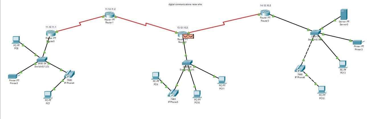
Figure 1: The full network scheme of communication analysis
Computers, routers, printers, servers, and ISPs are all used. Other twisted pairs are chosen even though the wires going to the router are fiber optic (Maria, 2018). All other settings are statically defined except for serial ports and router IP addresses, which are manually entered. The IP addresses and MAC addresses are matched as stated and “Fast Ethernet” is used for ingress. In this work, other situations have also been simulated. The network's devices offer data on the cabling local area network topology, and the simulation's package follower environment software includes this information. There are three types of data transfer methods: single point, multipoint, and multiple transfers. For a single-destination address transfer, multiple addresses must be delivered to multiple destinations.
The main scenario has been taken for the appropriate and proper simulation through network analysis and communication (Conrad et al. 2020). The main communication has been done for the eighth scenario as it has the proper IP configuration and PC configuration with a related Ethernet connection. The three routers provide a strong building block for managing the flow of data to the interconnected devices of the PC. The IP configuration of each router is necessary for supplying a proper internet connection to all the interconnected devices of the PC. If the IP configuration of routers isn’t proper then there is a huge possibility for the packet loss of the data and the internet connection can be hampered. Because of the packet loss of the data, the connection between the entire PC and the connected devices and the rate of the transfer of the data could get extremely low.
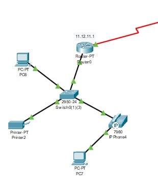
Figure 2: The main selected network communication diagram
Once the open short path can be executed with the protocol then the IP can be obtained from the DHCP server. The main communication has been derived with the connection of router 0. Then the switch has been connected to it. The interconnected PCs and printer and another IP phone with PC have been done with proper IP configuration. The network communication diagrams are obtained from the server of the “Cisco packet tracer”. The IP address can be fetched from the DHCP server after executing the open short path protocol in the server. The configuration of the IP address is also generated in the PC, printer, and phone which are interconnected with each other.
Discussion
The simulation demonstrates that there won't be any issues getting the results between a source package and the destination via the network. With the help of the Cisco Packet Tracer software, many topologies have been achieved by running a single NS simulation in reality. They are set up identically to the real router, switch, and hubs. The necessary devices have wide networks designed and configured. Dynamic Host Configuration Protocol for Computers has been found to have DHCP protocol set up and IP configuration.
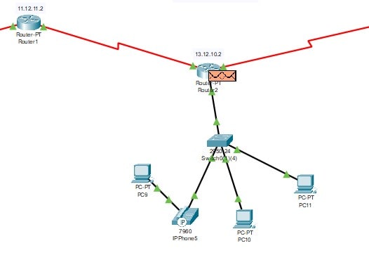
Figure 3: The main selected network of two routers
This scheme can be executed as the two router branches of the network communication system. Two routers are also interconnected. So communication can be executed properly through this network system. The configuration of the Router’s IP is necessary for setting up a proper network connection between them. From router 1 the main communication setup is generated to router 2 to supply the network connection to the entire PC and the printers. Router 2 is the secondary source of internet connection and the primary source of the network connection is router 1.
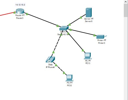
Figure 4: The main selected cluster network of router 3
Here, Router 3 has been derived and selected as a cluster internet system to hold the multiple network communication. This can help to make the network analysis for communication smooth and proper. From the above image, it is very clear that router 3 is providing the internet connection to many devices that needs an internet connection so a cluster of network communication system is generated from the network design which is created in the “Cisco Packet tracer”.

Figure 5: The scenario scheme of the network analysis
The figure above shows the total view of the CISCO Packet Tracer and the components with the main network scheme. The options of the components and the commands of successful communication or failed communication can be executed here. The image explains the total network build-up between all three routers which are connected to several PCs, servers, and electronic devices. The configuration of the IP of the three routers is necessary for maintaining a proper and steady internet connection without involving any packet loss of the data.
-(1)_657c22832d292.jpg?t=1702634114985)
Figure 6: The IP configuration of Router 0
The main router IP configuration is shown in the figure. The IP address of Router 0 is “11.12.11.1”.
-(1)_657c22b4a32d7.jpg?t=1702634164462)
Figure 7: The IP configuration of Router 1
The other router IP configuration has been shown in the figure. The IP address of Router 1 is “11.12.12.2”.
-(1)_657c22ddebf00.jpg?t=1702634205759)
Figure 8: The IP configuration of Router 2
The router2 configuration and IP address have been shown in the figure. The IP address of the Router 2 is “13.12.10.2”.
-(1)_657c230fd4e67.jpg?t=1702634255667)
Figure 9: The IP configuration of Router 3
The last main router IP configuration is shown in the figure. The IP address of Router 3 as the cluster is “14.12.10.2”.
The messaging system and the simulation are shown in the figure. The simulation can show the proper communication with network analysis in this diagram implementation. The above image shows the total simulation of the scenario for the network structure which is built between the three routers and PCs along with interconnected devices of the PC. The image explains the solution to the problem scenario and the simulation of this network communication structure is done in the “Cisco Packet Tracer”.
Conclusion
The numerous applicable cases have been evaluated with precedents in this study. Increasing these scenarios will provide several network breakthroughs in terms of advanced networks, network security, and network performance. Additionally, work-time simulations of static and dynamic IP configurations have been conducted. The simulation has been evaluated with a proper network diagram and scheme. The analysis has been completed with proper analysis and simulation and it has been executed using CISCO Packet Tracer.
References
Conrad, S.H., LeClaire, R.J., O'Reilly, G.P. and Uzunalioglu, H., 2020. Critical national infrastructure reliability modeling and analysis. Bell Labs Technical Journal, 11(3), pp.57-71.
Han, C. and Chen, Y., 2018. Propagation modeling for wireless communications in the terahertz band. IEEE Communications Magazine, 56(6), pp.96-101.
Lu, Y., Xu, X. and Wang, L., 2020. Smart manufacturing process and system automation–a critical review of the standards and envisioned scenarios. Journal of Manufacturing Systems, 56, pp.312-325.
Mansouri, N., Ghafari, R. and Zade, B.M.H., 2020. Cloud computing simulators: A comprehensive review. Simulation Modelling Practice and Theory, 104, p.102144.
Maria, A., 2018, December. Introduction to modeling and simulation. In Proceedings of the 29th conference on Winter simulation (pp. 7-13).
Schröder, F.A., Turban, D.H., Musser, A.J., Hine, N.D. and Chin, A.W., 2019. Tensor network simulation of multi-environmental open quantum dynamics via machine learning and entanglement renormalization. Nature Communications, 10(1), pp.1-10.
Wu, J., Chi, K.T., Lau, F.C. and Ho, I.W., 2018. Analysis of communication network performance from a complex network perspective. IEEE Transactions on Circuits and Systems I: Regular Papers, 60(12), pp.3303-3316.