- Advanced Structural Analysis Report Case Study
- 1. Detailed AutoCAD drawings for the roof floor and the rest of the floors with parking arrangement
- 2. 3D animation for the proposed plan
- 3. Producing schematic plan and section of structure beam and column layout
- 4. Embodied carbon for the structure of the building
Advanced Structural Analysis Report Case Study
Click here for expert assignment help from Native Assignment Help, a leading provider in the UK.
1. Detailed AutoCAD drawings for the roof floor and the rest of the floors with parking arrangement
A detailed AutoCAD drawing is done for a 7-story building along with the structural analysis of the building. It is designed in such a way that it can be suitable for both office and residential usage replacing a one-story building. One of the floors out of seven is used for parking. This building is situated in a high seismic zone. A swimming pool is provided in the drawing on the rooftop. The following building drawing is made as per the rules and regulations and the land which has been chosen is extremely valuable which is why waste area which means the elevators and staircase space is reduced (Hung et al. 2019). The indicative architecture plan for each flat is provided based on the overall building planning.

Figure 1: Detailed architectural plan of the flat
The main wall thickness of the building is 250 mm and the partition wall thickness is 120 mm and 150mm. The floor height of the building is considered 3m. 4m*2m rooms are mostly provided with windows, and doors of length 2100mm and 900mm width is provided. The detailed building plan is executed in AutoCAD. Parking arrangement is done in front of the main building of size 8*5.5m. This total building planning is done with a scale of 1:1. The Height of the rise and tread of the provided staircase is 150mm and 250 mm respectively. The width of the staircase is 900mm because this building can be used for both official and residential purposes. The angle of inclination of the staircase is 30 degrees. A slab thickness of 200 mm is provided here.
2. 3D animation for the proposed plan
The provided plan is executed in 3D for proper visualization. The LUSAS software fully features modeling which is based on the planning executed in Autocad. Various attributes like visualization and the creation of different features, load selection of all ranges of loads, data transfer models, geometric and material properties generation with boundary conditions, and automatic support distribution can be shown. LUSAS will help in the visualization of the overall 3D animation of the entire planning. It will provide comprehensive results from running multiple analyses. The forces and moments are calculated automatically along with the calculation of reinforcement for the shell elements and plates to minimize the reinforcement area (Gentry et al. 2022). 3D planning of buildings provides the overall look and layout of the building, which is an essential part of building planning. Along with that load calculation, the software determines interactive analysis of the model, interactive analysis of spectral response, calculation of fatigue response; strain energy, rubber stretches, and plastic work all. The overall result displays the 3D displacement and stress vectors, the 3D beam slice section, and the comprehensive graph for the standard spreadsheet package. Visualization of locations and global directions are also displayed in the software. Three-dimensional analysis can be very complex to execute (Wu et al. 2021).
3. Producing schematic plan and section of structure beam and column layout
The entire structural planning and design process is based on recent design laws. A drafted view of the building elevation with four sides is provided. Based on the map of the construction site, water bodies, buildings, and roads the entire schematic planning is done. A schematic plan of each floor is provided. Based on the provided information beams and columns are planned. The length of the beam is specified from center to center.
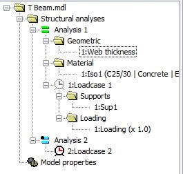
Figure 2: Attributes of the T beam
An architectural plan is provided which consists of two bedrooms, a staircase space, a dining room, and a drawing room, and the kitchen is merged, and a bathroom. That is the typical layout of a flat (Tang et al. 2020). Column, beam, and slab are designed so that the loads can be transferred accordingly. This overall process determines the perfect placement of the structural components and is referred to as structural layout.
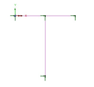
Figure 3: Detailed architectural design of the T beam
The basic measurement of the beam is 250*250mm and the column size depends on the total load applied to the columns. All the physical requirements, areas, and spaces required for the construction and the design of the building are provided. The overall seismic analysis is also required to be done based on the planning and designing of the structure. The beam and column layout of the building is done to transfer the applied load systematically from slab to beam and then column to footings. Beams are provided in such a manner that they are not aesthetically unappealing (Pepe et al. 2020). The overall building planning is based on 699.68 m2 of land, and 1.6 times the area of the entire land is used for this 7-storey building based on the local council guide. The ground floor of the building is only for parking facilities and is designed according to that.
4. Embodied carbon for the structure of the building
Throughout the process of designing a structure, the quantity of products and materials involved improves with accuracy. Embodied carbon is the total GHG emission of the entire building construction which also includes the amount of GHG produced from the transporting, extracting, manufacturing, and installing process of the various building materials at the site along with the operational emission based on the material used (Schabowicz, 2019). Embodied carbon is generally expressed with CO2 per kilogram of the material or product. This helps to scale and accelerate the reduction of carbon embodied in the built surroundings. Calculation of the embodied carbon depends on the area where the construction is taking place and the location of manufacturing the products and materials. Specification of all the materials is also a very important factor in calculating the embodied carbon.
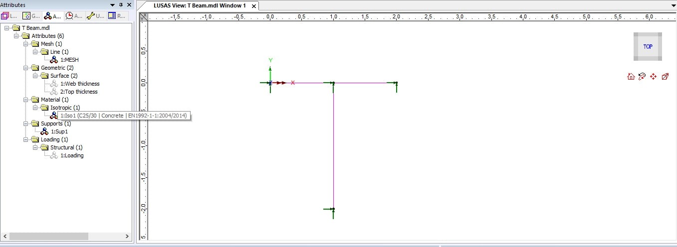
Figure 4: Software implementation in the LUSAS software
Based on this the value can be more or less. For substructures and superstructures where concrete materials are used the average carbon emission can be from 0.103-0.105 kgCO2e/kg. This value varies for precast concrete, mortar, and non-structural concrete.
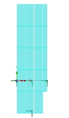
Figure 5: Direct method influence analysis of the T beam
For steel, this value varies from 0.7-2.8, and this value can differ for reinforcement bars, structural sections, plates, or galvanized sheets. For blockwork, the value of embodied carbon is 0.3 or less. Like these, the value of embodied carbon varies for different materials like brick, stone, timber, aluminum, glass, plasterboard, and paint (Gardner et al. 2019). This must be calculated in the early stage of the design so that changes can be made according to that.
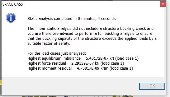
Figure 6: Static analysis result of the structure
The analysis of the designed structure has been done and determined the result of the force, moment, and equilibrium imbalance to fulfill the requirements of this project. Load case 1 has been saved in the software file to understand the implementation procedure which has been shown in this project as an image by the learner. The analysis of the building loan has been shown in the report file by conducting the software implementation in the space gass software.
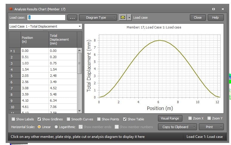
Figure 7: Graph of total displacement and position
The total displacement has been generated after putting the necessary attributes during the software implementation and determining the position and total displacement graph in this project to complete the requirements. Linear static and buckling analysis has been done by the learner and determined the global analysis of the displacement which has been required in this project. The table and graph of the analysis result have been shown in the report file hw fichas einem generated by conducting the software implementation in the space gass software the learner has observed the analysis result by conducting the designing part of the model by observing the requirements of this project.
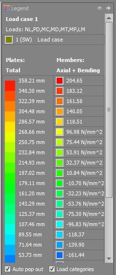
Figure 8: Analysis of load case of the design
The load case analysis has been conducted and shown in this project to observe the behavior of the structure, in which plated and members have been there which have been analyzed properly and shown the axial and bending analysis as an output in the report file. The plates and memes of the analysis result have been shown which have been generated after analyzing the loads.
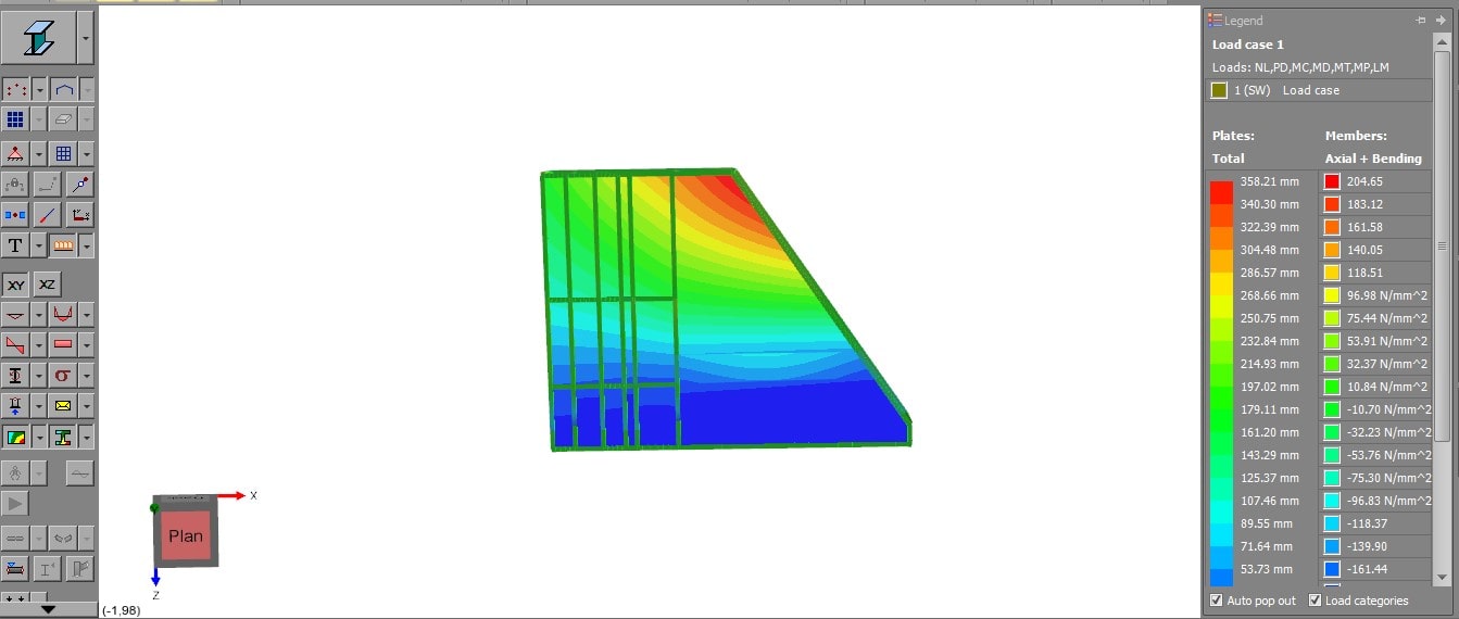
Figure 9: Structural analysis with required attributes of the building
The structure of the building has been shown in this report file which has been given in this project to complete the necessary queries. The proper analysis result has been shown in this image in which, on the right hand the maximum and minimum displacement has been generated after analyzing their structure. The attributes of the design have been also added in the designing section such as the members, plates, and nodes have been added during the section to understand the proper design of the model that has been given in this project.
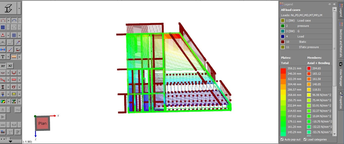
Figure 10: Number of nodes and plates of the designed model
The nodes and the plates have been connected properly which has resulted in a proper required design of the project. The joining functions of the nodes have been shown in this image to understand the implementation procedure that has been done in the Spacegass software. The shear force and bending moment analysis have been also done and the analysis result in this project is to determine the proper implementation procedure of the Spacegass software. The space gass software has been used in this project to determine the necessary analysis of the structure which has been designed by the learner and shown in this project to determine the competition of this project.
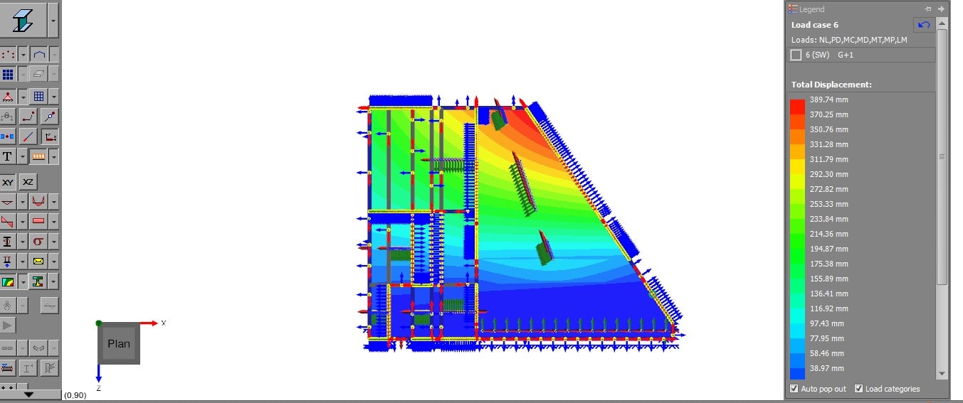
Figure 11: Analysis of the model
The total displacement of the structure has been shown in the project to determine the maximum and minimum displacement of the design. Thermal laid and pressure load also have been applied during the implementation procedure which has been generated in this software by the learner and added in the report file to show the analysis result of the implementation of the structural design. Axial and torsion forces have been also conducted by the learner and shown in the software file, which has been saved to fulfill the requirement of this project.
References
Gardner, L., 2019. Stability and design of stainless steel structures–Review and outlook. Thin-Walled Structures, 141, pp.208-216.
Gentry, T.R., Al-Haddad, T., Bank, L.C., Arias, F.R., Nagle, A. and Leahy, P., 2020. Structural analysis of a roof extracted from a wind turbine blade. Journal of Architectural Engineering, 26(4), p.04020040.
Hung, T.V., Viet, V.Q. and Van Thuat, D., 2019. A deep learning-based procedure for estimation of ultimate load carrying of steel trusses using advanced analysis. Journal of Science and Technology in Civil Engineering (STCE)-HUCE, 13(3), pp.113-123.
Pepe, M., Costantino, D. and Restuccia Garofalo, A., 2020. An efficient pipeline to obtain 3D model for HBIM and structural analysis purposes from 3D point clouds. Applied Sciences, 10(4), p.1235.
Schabowicz, K., 2019. Non-destructive testing of materials in civil engineering. Materials, 12(19), p.3237.
Tang, F., Ma, T., Zhang, J., Guan, Y., and Chen, L., 2020. Integrating three-dimensional road design and pavement structure analysis based on BIM. Automation in Construction, 113, p.103152.