Introduction: Advanced Structural Design And Bridge Engineering
Native Assignment Help provides assignment help to assist students in the research, writing and proofreading process.
The bridge is one of the most important structural components that has many uses in the daily life of transportation and the system of construction engineering. Mainly there are lots of systems that have many applications in the system of construction also construction is not that type of easy. To transport various types of vehicles from one side to another or to transport the system over any river it's necessary to construct the bridge in a manner and a system of fast traveling. There are lots of systems and there are plenty of different types of construction methods. There are lots of materials that need to be structurally sound in the manner of the system. This particular assignment needs to compare the system of the construction of the stipulated two bridges in the system of the constructional aspect and the design aspect of the matter. The discussion will be according to the comparison of the two bridges Fred Hartman Bridge and Millau viaduct.
Discussion
Part 1
Comparison of Two types of Bridges
If the consideration of the difference of the two types of bridges that generally applied in the construction as per the requirement and as per the demand of the locality and the client, there could be plenty of options that can be provided in the difference. Many systems that can be applicable in a particular system of construction have the system in the process that many systems have possible of different types of materials and different types of the load resistance property (Zheng et al 2019). In the system of comparison, the discussion system has many possibilities and many problems can occur. There could be many differences created according to the usage and the construction materials of the bridge so according to the construction material angle. The two types of bridge could be analysed as the Cable Bridge and Cantilever bridge.
- Cable Bridge: The cable bridge or suspension bridge or cable stayed bridge is constructed for the solving purpose occurring the load of the large span of the particular system. The stipulated bridge deck is vertically hanging with the system of the cables in the system of the support of the piers or the abutments. In the system of the application there are main cables that connect the main bridge deck with the system of the bolt or the rivet or many other stem with the cable. The suspender cables are made of high carbon steels and many more advanced quality meats. The bridge deck can be constructed as per the demand and the cost simulation of the projects. It can sustain a large amount of the load as the system of the construction needs to be implemented at higher bearing capacity of the soil. If considering the advantages of the bridge that is
- It can sustain a longer span of the bridge deck
- This type of bridge can reduce the number of materials.
Disadvantages-
- >
- Higher stiffness required in the process of the bridge deck sustainability to reduce wind related vibration
- Cost of the foundation is high.
- Cantilever Bridge: The concept of the cantilever system is directly applied in this system of the bridge. Acting as the system of cantilever, this type of bridge is easy to construct and easy to maintain the system of the application of the system of the load sustainability. In this particular system there is usage of the truss balance system in the possible way of the system that has many steel structural joints that have many systems. Consisting of anchor arm, cantilever arm, Suspended arm has the huge possibility in the system of the load sustain (Wang et al 2022). Also this type of bridge was used for many centuries for the transportation purposes in the particular system. Its need to assure structural stability in the process of the maintenance of the system in the way of the nature and there are lots of the system that the maintaining stability needs to be implied. Only drawback of the particular system is it may have some weathering effect in the long run.
Part 2
Fred Hartman Bridge
The Bridge was constructed in Texas USA from 1986 to 1996 to join the Baytown and La Porte. The bridge is a constructional system of a cable-stayed bridge and has a system of different types of the system of different types of spans but the allover span of the bridge is a different system of calculation and there is mainly the system of comparison of the structural details (Zhou et al 2020). Consists of a span of the 381 m in the main span there are lots of continuous systems of the symmetrically support system in the possibility Consists of the lots of the system in the possibility of the concrete pier and there are lots of anchor porters connected in the past of the 305 mm diameter in the system.
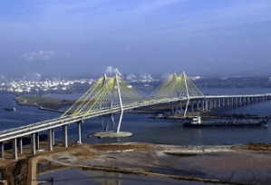
Figure 1: Fred Hartman Bridge
In this system, the system if the structural design has been considered then the system of the bridge deck is as large as the system of the possibility of the equal direction of the system of the possibility. Steel is required to be placed either diagonally and each direction placed horizontally in the system. Considering vertical stiffness which is one of the most important systems in this system that have the possibility in the space of restraining the load. Also, there is a structural roadway of the concrete which is 200mm thick in the present scenario of the bridge. Also, there are lots of systems that can be present in a particular way (Invernizzi et al 2019). The Cable anchorage way distance is 15.2m. If the summary of the particular system needs to be considered in the system that possibility can be systemized in the system. If summarized the total design system then it's been visible.
- Type of support: Cable
- Deck of the bridge: Reinforced concrete
- Deck of the viaduct: Reinforced Concrete
- Cable anchor distance: 15.2m
- Connection of the Box girders: 15.4m
- Steel bars used: 18mm
Millau Viaduct
This is also a bridge of the system of cable restraining in the system of retaining the load, the same type of bridge that has many possibilities in the system of the conclusions. As per the general information of the system, the beginning of construction started around the time of 2001 and it has an end of the work around 2004, which takes only the stipulated 38 months to the completion of the particular job(Sheng et al 2021 ).
This job is a multiple-span-based cable bridge that has many types in the system of the application. Located in France, the system of the bridge is over the Tarn River in the city adjoining a 75-meter motorway that is related to the information center of Milan. Considering the technical information of the particular bridge the total length is given as 2460m Total span length of the particular system span length of the particular deck is given as 204m for each. Each of the pier heights is about 94 to 244 meters according to the requirements of the heights that need to sustain the bridge in the particular system (Alocci and Valvo 2019). There are lots of systems in the design specification of the data and there are lots of the systems in there. According to the system of the design, there are lots of concrete systems near about 13000 m3 and there is a reinforcing system of the possibility of 1300 t in the foundation. There are many systems in the projections. The total concrete volume in the pyres is 53000m3. The stay cables that are needed in the system are 1500t in the connection of the system. There are lots of other systems that have the system possibility of the particular systematics. The total cost of the given project that needs to be implemented is 300 Million euros.
If considering the design summary and short briefing of the system of this particular bridge then the data will get
- Type of support: Cable support
- Deck of the bridge: reinforced cement concrete
- Deck of the viaduct: Reinforced cement concrete
- Cable anchorage distance: 20 m
- Connection of the Box girders:21.5m
- Steel bars used:25 mm
In the above system of the minimal comparison of the bridge and the system of the possibility of the particular system of the short briefing of the bridge and there are lots of the systems in the possibility that there are many systems of the calculation of the design data in the system has many aspects in the system of the possibility in the system and there are many drawing and the annotation and the analytical calculation of the system of the construction that have many aspects of the system(Sheng et al 2021). If considering the types of the system of the bridge that has been allocated and discussed above with the system of the completion then this kind of bridge is said to be a Cable suspension bridge.
Qualitative discussion and comparison
Every construction has the system of the concepts of the system of design implementation, the design data, and the design specification (Pu et al 2019). As per the completion system, there are lots of issues and problems with the system. To consider the design and the analysis everyone should have an idea of the system of the application in the system and there are lots of options that need to be answered during the design of the particular system of the application in the implementation of the design. Mainly these two cable bridges that have a briefing in the system of the application on the construction the available notice data and the system of the application of the construction materials as per the requirements needs to be inserted in the system of the application (Zhou et al 2018). Also, the application of the cost in the particular way of fitting needs to be implemented in the system.
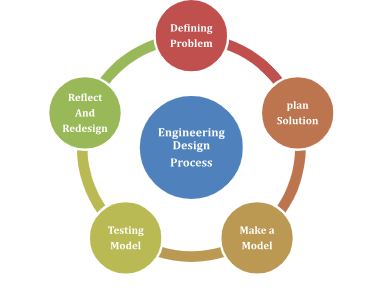
Figure2: Design process thinking
In this system of construction, two types of cable bridge construction are constructed in their stipulated time span. There are lots of systems in the design briefing. As the summary of the construction is given earlier there are lots of systems that need to be implemented in the way of the system. In the system of the application, the bridge deck span length of both systems span over 300 meters. If we considered the application and the design application of the system. If the differentials are noted in the system of the comparison table then lots of the design briefing and the data will come out.
|
Property |
Fred Hartman Bridge |
Millau Viaduct |
|
Year of construction |
1986-1995 |
16.10.2001-14.12.2004 |
|
Location |
Bay town and La Porte Texas |
Millau, France, and Creissels |
|
Project type |
Cable stayed bridge with fan system |
Cable stayed bridge |
|
cost |
$ 91.3 million that have total application |
Euro 300000000 |
|
Participants |
Texas city council of transport |
Republic of France the administration of the highway and the traffic control board. |
|
Total Length |
4185m |
2460m |
|
Main span |
381m |
342 |
|
Length |
146.9-381.0-146.8 |
204m-342m-204m |
|
Deck width |
47m |
32.050 |
|
Wind load |
47m/s |
|
|
Live load |
17 tons |
100MN |
|
Pylon Height |
129.84 |
88.92m(above deck) 343m(max above ground) |
|
Materials |
Reinforced and Steel structure and Pre stressed concrete in pier and the Deck |
Steel girder deck. Prefabrication in the system of their system of cast in situ method concrete at pier. Steel girder is made in the factory |
|
Deck Construction type |
Reinforced cement concrete with 20mm dia of steel bars |
Steel rebar girder |
|
Deck approach Viaduct |
Reinforced cement concrete with 16 mm dia steel bars |
Reinforced cement concrete |
|
Pire details |
18 mm dia with 15 mm crosswise across the span and the system. Minimum 2.2% of the reinforcement of the application |
Varying cross section of the piers Movement of the system by prefabrication in the system in the place. Almost 2100 stiffness panels in the system.75 welders needed in the pre-assembling of the system. |
|
Cable details |
15.2mm 25mm clear span |
1500 ton carbon steel fiber used |
|
Road construction details |
100 mm thick wearing layer |
300 mm tick wearing layer |
|
Girder distance |
400 |
350 m |
|
Slab thickness |
200mm |
|
|
Torsional stiffness |
5.4m |
6.6 |
|
Foundation bearing capacity |
Alluvial soil in the channel , bars of the system is 40 mm bearing capacity 200 t |
Moderate system of the soil bearing capacity is said to be 250 t |
Table: Comparison of the Design data
Part 3
Critical discussion of the Bridge Data
In the system of the design data there are various types of the system that have the possibility that there is a system of the structural differences in their system of the calculation of the system. The main difference between the structural ability in both of the bridges in the system is that the Fred Hartman Bridge is constructed as a reinforced cement concrete bridge in the system for the constructional materials purpose (Yang et al 2020). Also there are lots of the design implementation and the possibility of the different challenges that need to be considered in the particular project, one of the above is that is more important is the soil capacity that has many delays because of the alluvial soil. As Texas is a very populated city there are lots of systems that need to be inserted in the system as there is some design data that needs to be consulted as below.
- Cast in situ fabrication of the concrete.
- Pylons of the system are prefabricated systems of the pier and many systems.
- Length is the system's main space that has many systems that have 381 m which is mainly heavy in the system and have many possibilities in the seismic load and wind load attack by the application of the system.
- Stipulated deck width having 47 that is calculated through the percentage of the system of the wind and the system of the possibility and there are lots of the sway analysis and there are many system that have the possibility that have in the process of the sway analysis
- The road way and the bridge is designed as per the recommendation of the AASHTO as per the classification of the materials and the system of the application dimension method is used for the completion of the system.
- Bridge system has many systems that have a span of 381 m and there are many systems that can be applied.
- The whole bridge system is built in the system of the Reinforced concrete structure in cast in situ in some part and precast in the pier part of the bridge, There was a necessity in the installation of the system of the prefabrication factory in the system of the construction nearer the construction and the foundation system.
- Data has been found according to the foundation system of the bridge, which is said to be a floating foundation in the system. Also the bridge is constructed over alluvial soil, at Houston ship channel. There are prestressed driven piles that have been used in the foundation of 50 cm dia and 40 m long piles. Total 130 no piles are used in the system of the construction of the bridge. As per the soil test the bearing capacity of the soil is found to be 200 tons (Yang et al 2020). The pile cap of the particular system is 3.6m deep and the pile cap is bound by the 40 mm dia reinforced steel bars.
- According to the tower of the bridge where the system of cable will be stuck for resisting the load is nearer to the deck. The leg has a cantilever system in the jump on the system. And there are lots of the system and the section is nearer to 4.5 m width. Two layers of reinforcement of the layer in the leg with 305 mm and there are reinforcement gaps is 150 mm. In the reinforcement section there are 25mm dia bars used in the system which creates the weight of the reinforcement of the system is18 ton. The bars are coupled in the system of squeeze sleeves in the predated system of the application. There is a system in the process of using a superplasticizer in the process.
- Beam in the system is used as a steel girder, for the economic sustainability the pre casted steel girders are manufactured in the city of Cape Town, and the system is supplied by the ship through sea. Beams were attached with the field welding in the system of the application of the particular way.
- Considering the stay cables that have been used in the system are used in the system were selected in the system. a 15 mm galvanized system is used in the system of the application system(Zhang et al 2022). Cables are listed in the girder system of the application. Several anchorage boxes are installed in the system and there are lots of processes. Anchorage boxes in the system and there are many systems that have the system and there are lots of the cables of the system that are attached in the box in the stipulated system.
- According to contractors alternate there are lots of the system in place that there is an increase of the additional weightage in the system that have increased by 640 tons that have increased at the total weightage of the steel.
The Millau Viaduct has almost the same system and the category of the construction, just the difference of the implemented materials and the system of the application that have many perspectives of the design data that have many assumptions in the system of the application in the construction. This is also a Multi span cable stay bridge with a semi fan system attached in the process. Located in the Millau and the joining of Creissels the bridge is constructed to be a part of the motorway 75 in the system of the application.
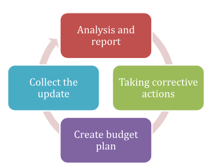
Figure3: Cost Control Process
The bridge is said to be in the light weight system of the slenderness of the beam as the system is viable to 36 tons against 120 tons. Also there is data that had been found as the 43 tons of the steel is already fabricated in the system of the fabrication, at the lower and the auxiliary pillars that had been installed in the system. If considered the critical data that had been found that
- This is a multi-span cable stayed bridge with a semi attached fan system. Used for the motorways and roadway proposed on the application system.
- Total design specification is given as total length 2460m with the horizontal radius of the curvature is 20000 m. the deck depth that have in the system is 4.20m and there is a height of the valley floor above water is given as 270 m. the total width of the system is 270m
- As the bridge structure and deck have different gradients and different heights there are several heights of the pier and there are lots of the system of different heights that are already installed in the system.
- Volume of the earth work is said to be in the system of 350000m3
- Piles have the concrete volume of 6000 m3 with the consisting reinforcing steel 1200t
- Given steel Cable of the system is 1500 tons with attached in the box system at the certain distance of the25 m
- The deck consists of precast steel with a prefabrication system of the application in the system. The consisting abutment is about the system of pre casted concrete of the system. Box girder is applied in the system of the fabrication (Nzarpour et al 2023). There is 230 m height from the river in the system of the application of the system
- There are about 2100 stiffened panels to resist slenderness.
- The total system of the application of the reinforcement system is 10000 tons
- Temporary work is done almost 7500m3 concreting and 400t of the steel.
Conclusion
As the data has been received in the system there are lots of the system. Basically in the possibility in the system of the construction things needs to be system. There are many things that have to be taken into consideration according to system information. In the critical analysis of the system there are lots of the system in the bridges that are compared in the analysis in the system. If we consider the cost of the different bridge then the system is considered the cost of the construction of the Fred Hartman Bridge is 92 million dollar whereas the cost of the cost of Millau Viaduct is 314 million dollar. For the design of the particular system of the bridge, there are lots of systems that need to be commenced like what will be the span of the bridge? What is the design of the deck, what will be the particular design application of the load, and what is the system of load definition of the system, also what is necessary and the location of the bridge that needs to be constructed in the place.
References
Journals
Alocci, C. and Valvo, P.S., 2019. Feasibility study of a hybrid FRP-steel cable-stayed pedestrian swing bridge. Engineering Structures, 189, pp.359-372.
Graybeal, B., Brühwiler, E., Kim, B.S., Toutlemonde, F., Voo, Y.L. and Zaghi, A., 2020. International perspective on UHPC in bridge engineering. Journal of Bridge Engineering, 25(11), p.04020094.
Han, Q., Wen, J., Du, X. and Huang, C., 2019. Seismic response of single pylon cable-stayed bridge under scour effect. Journal of Bridge Engineering, 24(6), p.05019007.
Invernizzi, S., Montagnoli, F. and Carpinteri, A., 2019. Fatigue assessment of the collapsed XXth Century cable-stayed Polcevera Bridge in Genoa. Procedia Structural Integrity, 18, pp.237-244.
Javanmardi, A., Ghaedi, K., Huang, F., Hanif, M.U. and Tabrizikahou, A., 2021. Application of structural control systems for the cables of cable-stayed bridges: state-of-the-art and state-of-the-practice. Archives of Computational Methods in Engineering, pp.1-31.
Li, S., Dezfuli, F.H., Wang, J.Q. and Alam, M.S., 2018. Displacement-based seismic design of steel, FRP, and SMA cable restrainers for isolated simply supported bridges. J. Bridge Eng, 23(6), p.04018032.
Nzarpour, V. and Gholizadeh, S., 2023. DESIGN OPTIMIZATION OF CABLE-STAYED BRIDGES USING MOMENTUM SEARCH ALGORITHM. Iran University of Science & Technology, 13(1),
Pu, Q., Liu, J., Gou, H., Bao, Y. and Xie, H., 2019. Finite element analysis of long-span rail-cum-road cable-stayed bridge subjected to ship collision. Advances in structural engineering, 22(11), pp.2530-2542.
Pu, Q., Liu, J., Gou, H., Bao, Y. and Xie, H., 2019. Finite element analysis of long-span rail-cum-road cable-stayed bridge subjected to ship collision. Advances in structural engineering, 22(11), pp.2530-2542.
Sacks, R., Kedar, A., Borrmann, A., Ma, L., Brilakis, I., Hüthwohl, P., Daum, S., Kattel, U., Yosef, R., Liebich, T. and Barutcu, B.E., 2018. SeeBridge as next generation bridge inspection: overview, information delivery manual and model view definition. Automation in Construction, 90, pp.134-145.
Sheng, X., Zheng, W., Zhu, Z., Yan, A. and Qin, Y., 2021. Ganjiang Bridge: A high-speed railway long-span cable-stayed bridge laying ballastless tracks. Structural Engineering International, 31(1), pp.40-44.
Sheng, X., Zheng, W., Zhu, Z., Yan, A. and Qin, Y., 2021. Ganjiang Bridge: A high-speed railway long-span cable-stayed bridge laying ballastless tracks. Structural Engineering International, 31(1), pp.40-44.
Wang, X., Wang, L., Wang, H., Ning, Y., Huang, K. and Wang, W., 2022. Performance evaluation of a long-span cable-stayed bridge using non-destructive field loading tests. Applied Sciences, 12(5), p.2367.
Yang, Y., Wang, X. and Wu, Z., 2020, June. Life cycle cost analysis of FRP cables for long-span cable supported bridges. In Structures (Vol. 25, pp. 24-34). Elsevier.
Yang, Y., Wang, X. and Wu, Z., 2020, June. Life cycle cost analysis of FRP cables for long-span cable supported bridges. In Structures (Vol. 25, pp. 24-34). Elsevier.
Zhang, J., Zhang, M., Jiang, X., Yuan, R., Yu, J., Zhou, Y. and Qin, S., 2022, March. Causes and control to lateral displacement of the main girder in the super-long-span cable-stayed bridge with transverse asymmetry dead load. In Structures (Vol. 37, pp. 168-184). Elsevier.
Zheng, Z. and Ding, N., 2019, May. Design and implementation of ccrobot-ii: a palm-based cable climbing robot for cable-stayed bridge inspection. In 2019 International Conference on Robotics and Automation (ICRA) (pp. 9747-9753). IEEE.
Zheng, Z., Yuan, X., Huang, H., Yu, X. and Ding, N., 2018, July. Mechanical design of a cable climbing robot for inspection on a cable-stayed bridge. In 2018 13th World Congress on Intelligent Control and Automation (WCICA) (pp. 1680-1684). IEEE.
Zhou, M., Lu, W., Song, J. and Lee, G.C., 2018. Application of ultra-high performance concrete in bridge engineering. Construction and Building Materials, 186, pp.1256-1267.
Zhou, Z., Alcalá, J. and Yepes, V., 2020. Bridge carbon emissions and driving factors based on a life-cycle assessment case study: Cable-stayed bridge over Hun He river in Liaoning, China. International Journal of Environmental Research and Public Health, 17(16), p.5953.
Go Through the Best and FREE Samples Written by Our Academic Experts!
Native Assignment Help. (2026). Retrieved from:
https://www.nativeassignmenthelp.co.uk/advanced-structural-design-and-bridge-engineering-20662
Native Assignment Help, (2026),
https://www.nativeassignmenthelp.co.uk/advanced-structural-design-and-bridge-engineering-20662
Native Assignment Help (2026) [Online]. Retrieved from:
https://www.nativeassignmenthelp.co.uk/advanced-structural-design-and-bridge-engineering-20662
Native Assignment Help. (Native Assignment Help, 2026)
https://www.nativeassignmenthelp.co.uk/advanced-structural-design-and-bridge-engineering-20662
- FreeDownload - 44 TimesCO1409 Payroll System Using C++ Assignment Sample
CO1409 Payroll System Using C++ Assignment Example Introduction The idea...View or download
- FreeDownload - 45 TimesBMHP5023 - Introduction to Physiology
Introduction to Physiology Assignment INTRODUCTION The study of physiology is...View or download
- FreeDownload - 38 TimesFinancial Accounting Assignment Sample
Financial Accounting Assignment Sample Introduction Getting the best free...View or download
- FreeDownload - 46 Times7ENT2033: Design of Steel and Composite Structures Assignment Sample
Design Options Option 1: Centralised Beam Grid Layout It has a balanced...View or download
- FreeDownload - 40 TimesContemporary Issues in Accounting and Finance Assignment Sample
Introduction: Contemporary Issues in Accounting and Finance Assignment In the...View or download
- FreeDownload - 37 TimesCOM5024 Advanced Databases Assignment Sample
Database Design and Implementation Report Assignment Introduction The design,...View or download
-
100% Confidential
Your personal details and order information are kept completely private with our strict confidentiality policy.
-
On-Time Delivery
Receive your assignment exactly within the promised deadline—no delays, ever.
-
Native British Writers
Get your work crafted by highly-skilled native UK writers with strong academic expertise.
-
A+ Quality Assignments
We deliver top-notch, well-researched, and perfectly structured assignments to help you secure the highest grades.