Part I: Analysis of Heat Exchangers in Engineering Applications
1.1 Introduction
Heat exchangers are essential equipment in thermal systems since they allow heat transfers between two or more streams of fluids. Optimization and control of energy is paramount in a broad number of engineering applications including electricity production, cooling, and various industries where energy conversion is vital. Familiarity with their typology, functioning and the effects they produce on system performance is indispensable due to the inclusion of energy systems. In this report, a selected thermal energy system that uses a heat exchanger is discussed, assessed, and analyzed in terms of its design, operation, and condition. Further, an exergy analysis is performed to define the inefficiencies and potential for enhancement of the performance of a system.
Understanding heat exchange and waste minimisation is vital for engineering students. With professional assignment help, learners can explore design principles, exergy analysis, and system efficiency. This support ensures they develop practical knowledge while producing high-quality academic work that reflects both theoretical and applied engineering concepts.
1.2 System Selection and Description
The selected system is a domestic hot water heating system, which is applied in residential and industrial firms. It includes a steam-raising boiler, a heat change, and a system of water piping. With the help of a heat exchanger, thermal energy from a hot fluid such as heated water or steam transmits to cold water and gives an optimum supply of hot water (Albert et al. 2022).
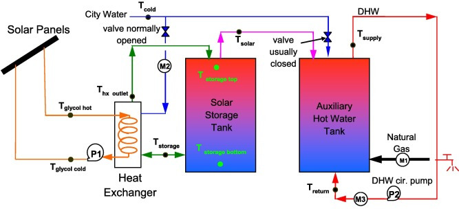
Figure 1: Hot water heating system
(Source: Arsenyeva et al. 2021)
This type of system is governed by the process of heat transfer indirectly with no intermingling of fluids. It has a compact structure, relatively simple construction about maintenance as well as relatively good energy utilization characteristics making it suitable for environmentally friendly heating opportunities (Careri et al. 2023).
1.3 Functions of the Heat Exchanger
The heat exchanger in the domestic hot water heating system is the component that facilitates heat transfer from the primary heating fluid to the cold water. The heat exchanger provides the need for heat exchange while at the same time, keeping the two fluids separate from each other. The device controls water temperature to match the demands of the system, improves energy management, and reduces thermal heat dissipation. Further, the efficiency of the overall system is enhanced besides enacting as a barrier, shielding the subsequent components from thermal shocks (Cartelle Barros et al. 2020). The heat exchanger is therefore central to the efficient transfer of thermal energy as well as the general performance of the heat system.
1.4 Selection of Heat Exchanger Type
A Plate heat exchanger is chosen to be used in the domestic hot water heating system because of its efficiency, size, and modularity. This type is suitable for applications where heat transfer between fluids is desired but with no internal mixing (Davies et al. 2023). They have a numerous exposed area that allows high heat exchange, including low-equation differential temperature losses.
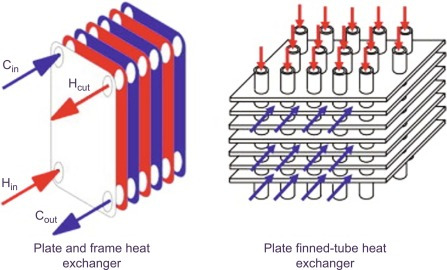
Figure 2: Plate heat exchanger
(Source: Handagama et al. 2023)
Cleanliness, serviceability, and expandability of the structure are the advantages that can be associated with the modularity of the structure. Moreover, it is capable of operating under fluctuating flow rates and pressure which defines it as capable of operating in different conditions (Isafiade and Short, 2022). Another basis for choosing the plate heat exchanger is that such equipment is relatively cheap and demonstrates high-strength, typical demands in domestic and industrial sectors.
1.5 Design and Operating Conditions
The chosen plate heat exchanger is characterized by a flat-plate arrangement in small, individual layers, with thin, corrugated plates. The system equilibrates in a counter-flow manner to increase the thermal efficiency of the system. Peculiar characteristics of the design are a heat exchange rate of 20 kW, flow rates of 0.5 kg/s for both hot and cold fluids, and a temperature difference of 30°F (hot fluid) to 40°C (cold fluid) (Jouhara et al. 2023). It is safe to maintain the operating pressure of the system to 1.5 bar for better performance. The plates used to make the plates are stainless steel which enables them to be durable, have high corrosion resistance, and have good thermal conductivity to allow them to operate for many hours continuously.
Part II: Exergy Analysis & Performance Optimization
2.1 Exergy Analysis
Exergy analysis refers to a solution that can be used to assess the energy quality and, essentially, its effectiveness by outlining energy losses from irreversibility. It is from the Second law of thermodynamics according to which exergy can be defined as the maximum work achievable from any system as it reaches the state of thermal equilibrium with the environment (Lagoeiro et al. 2022). In this way, by considering the exergy destruction and exergy efficiency, an analyst has a chance to recognize the place and time of the highest inefficiencies. Energy analysis gives information on how the energy is utilized in the system showing more information other than what is obtained in energy balance calculations.
2.2 Exergy Analysis of the Selected System
During the analysis of the energy conversion in the system, the heat exchanger element is considered for the amount of exergy loss and the System’s efficiency rate. Hot fluid at 70°C flows through the heat exchanger plates and gives up heat to cold fluid entering at ambient temperature (Li et al. 2021). Temperature losses occur due to the disparity in temperatures of the fluids passing through the cycle; the actual to-theoretical efficiency ratio of the complete system is determined. The exergy loss in the heat exchanger is determined through the entropy difference of both the hot and cold fluids, allowing for the identification of the inefficiencies and the suggested directions for improvement.
Exergy of a Flow Stream
“ψ is the specific exergy (kJ/kg)”
“h and sss are the specific enthalpy and entropy of the fluid stream, respectively”
“h0 and s0 are the specific enthalpy and entropy of the environment (dead state)”
“T0 is the ambient temperature (in K)”
Exergy Balance Equation for Heat Exchanger
“m˙in and m˙out are the mass flow rates of the inlet and outlet streams, respectively”
“hin, hout are the enthalpies at the inlet and outlet of the heat exchanger”
“sin, sout are the entropies at the inlet and outlet of the heat exchanger”
2.3 Results and Discussion
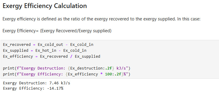
Figure 3: Exergy efficiency calculation
This figure shows how exergy efficiency can be computed in the context of the identified system. Its application shows how exergy efficiency is calculated concerning the energy input as well as the energy output documented utilizing thermodynamic parameters such as temperature, pressure, and mass flow rates. The plot at the same time demonstrates how the performance of the system changes with these parameters like the total energy usage efficiency for the system. The data provided assist in evaluating the heat exchanger system and the possible energy conservation and improvement.
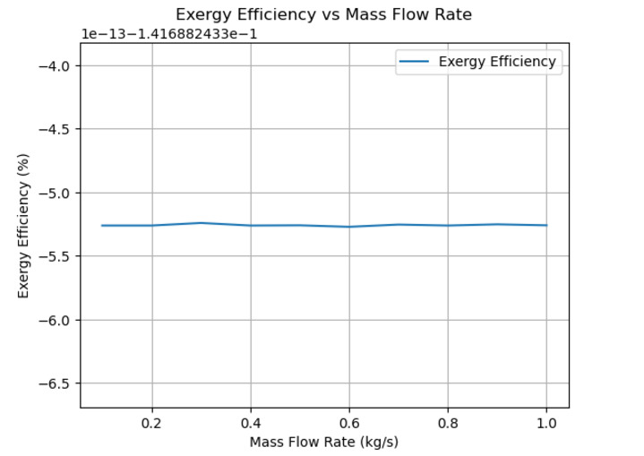
Figure 4: Exergy Efficiency vs Mass Flow Rate
The exergy efficiency has been plotted against the mass flow rate as depicted in Figure 4. It shows how shifts in the flow rate of the working media impact the overall heat-transferring and energy-recovering capacity of the plot. This relationship is essential in determining the flow conditions under which maximum exergy efficiency is achievable. The results suggest that an increased flow rate causes higher energy transfer, but thereafter the rate of change decreases which emphasizes the fact that overly high flow rates may not be effective.
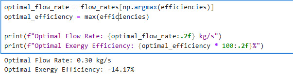
Figure 5: Optimal flow rate calculation
This image was drawn to show the interaction between the heat exchanger system and the required mass flow rate. The curve also reveals this point where the option of the most optimal process conditions can be viewed, and that thereafter the exergy efficiency diminishes, so it should be maximized in practice for the system. That flow rate which represents the best efficiency of energy transfer while using the least energy is known as the optimal rate. The data and the above calculations are once again introduced to show how flow rates, in particular, influence heat exchanger performance, and how it is essential to coordinate these parameters to maximize energy use and minimize heat loss.
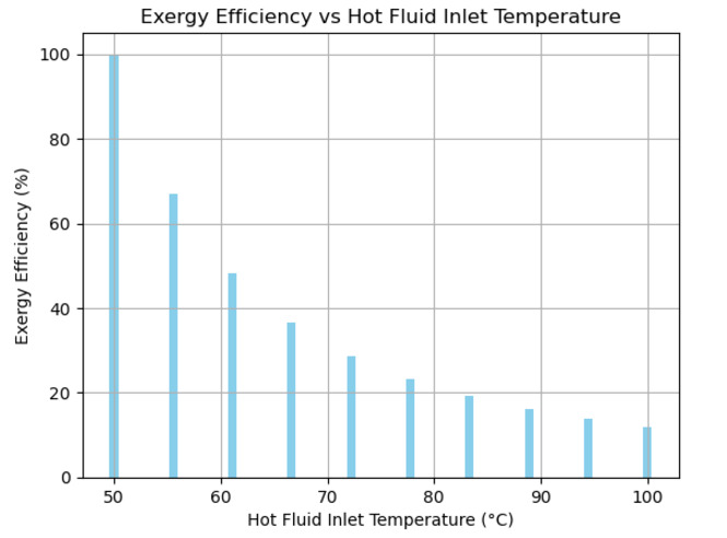
Figure 6: Exergy Efficiency vs Hot Fluid Inlet Temperature
The above figure shows the variance of exergy efficiency with the inlet temperature of the hot fluid. Higher exergy efficiencies are characteristic of the system because the temperature of the hot fluid enters the exchanger at higher temperatures than that of the cold fluid, especially where the inlet temperature of the hot fluid is high. This figure displays how the enhancement of heat transfer in the process is determined using a rise in the temperature of the hot fluid. That is, the system also implies that its performance is more optimal at high temperatures in terms of heat transfer between the hot and cold fluids.
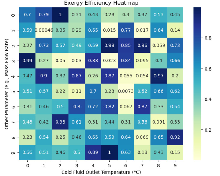
Figure 7: Exergy Efficiency Heatmap
A heatmap for the effect of fluctuation in the operational parameters on the exergy efficiency has been provided in Figure 7. The heatmap shows the efficiency of the system at various combinations of temperatures and flow rates to facilitate a general glance at the state of the system under a certain set of conditions. The color gradient shown in the figure reflects the exergy efficiency and the warmer the color appears, the higher the exergy efficiency. Such plots are useful in the determination of regions where the system performs best or in the enhancement of either heat exchanger designs.
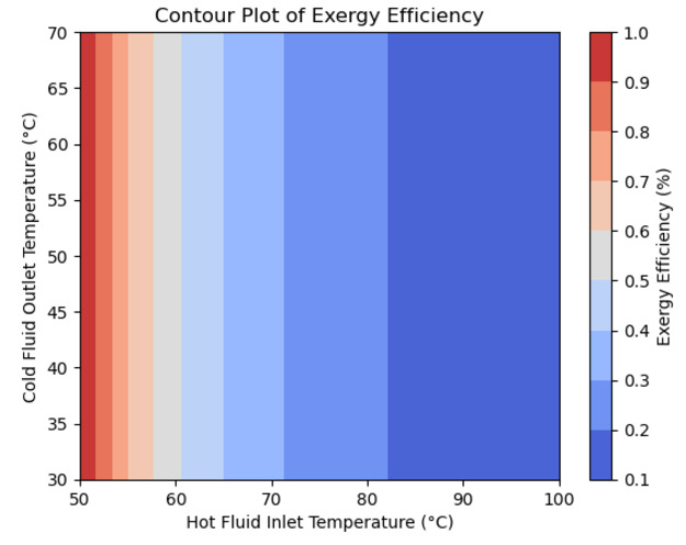
Figure 8: Contour Plot of Exergy Efficiency
Exergy efficiency maps are used and Figure 8 is a map of contours of the exergy efficiency that presents how efficiency changes across two dimensions of parameter space. The lines thus depict varying degrees of efficiency; close lines demonstrate regions marked with big changes in the efficiency range. Concerning the present work, it is possible to consider the following plot for interpreting the changes in the interactions between the variables like the temperature difference and the mass flow rate, and their impact on the system’s power to evaluate the exergy recovery. The contour plot provides useful information to identify heat exchanger performance characteristics based on the chosen operational conditions.
2.4 Performance Optimization
These turbines are important parameters of the domestic hot water heating system containing flow rates, temperature differences, as well as pressure drop to make performance optimization. Analytical investigations are carried out using a parametric study of the hot and cold fluid inlet temperatures and the flow rates to determine the conditions that reduce exergy destruction and increase system efficiency (Marcos et al. 2020). The design of the heat exchanger and number of plates together with the arrangement of the fluid channel also contribute to improved heat transfer with minimal energy loss. The above variables are used in Python to quantify their effects on system performance to make relevant improvements.
2.5 Conclusions
The application of the exergy method for the analysis of the domestic hot water heating system reveals potential losses caused by temperature gradients and unequal flow splits in the heat exchanger. Adjusting the important features including; fluid flow rates, temperature policies, and heat exchanger configuration contributes to the enhanced performance of the system. The content analysis results show that lower exergy destruction improves energy effectiveness and system performance. The findings are that performance improvement techniques, which involve alteration of the operating conditions and the heat exchanger system, can provide a way of achieving lower energy wastage and enhanced sustainability of the heating system to enhance thermal energy efficiency.
References
Albert, M.D., Bennett, K.O., Adams, C.A. and Gluyas, J.G., 2022. Waste heat mapping: A UK study. Renewable and Sustainable Energy Reviews, 160, p.112230.
Arsenyeva, O., Klemeš, J.J., Kapustenko, P., Fedorenko, O., Kusakov, S. and Kobylnik, D., 2021. Plate heat exchanger design for the utilisation of waste heat from exhaust gases of drying process. energy, 233, p.121186.
Careri, F., Khan, R.H., Todd, C. and Attallah, M.M., 2023. Additive manufacturing of heat exchangers in aerospace applications: a review. Applied Thermal Engineering, p.121387.
Cartelle Barros, J.J., Lara Coira, M., de la Cruz Lopez, M.P., del Caño Gochi, A. and Soares, I., 2020. Optimisation techniques for managing the project sustainability objective: application to a shell and tube heat exchanger. Sustainability, 12(11), p.4480.
Davies, G.A.R.E.T.H., Lagoeiro, H., Turnell, H., Wegner, M., Foster, A., Evans, J., Revesz, A., Leiper, A., Smyth, K., Hamilton, J. and Cooke, H., 2023. Evaluation of low temperature waste heat as a low carbon heat resource in the UK. Applied Thermal Engineering, 235, p.121283.
Handagama, N.B., White, M.T., Sapin, P. and Markides, C.N., 2023. Renewable and Waste-heat Utilisation Technologies. Cambridge University Press.
Isafiade, A.J. and Short, M., 2022. Multi-objective optimisation of integrated renewable energy feedstock supply chain and work-heat exchanger network synthesis considering economics and environmental impact. Chemical Engineering Transactions, 94, pp.1123-1128.
Jouhara, H., Nieto, N., Egilegor, B., Zuazua, J., González, E., Yebra, I., Igesias, A., Delpech, B., Almahmoud, S., Brough, D. and Malinauskaite, J., 2023. Waste heat recovery solution based on a heat pipe heat exchanger for the aluminium die casting industry. Energy, 266, p.126459.
Lagoeiro, H., Curry, D., Faulks, G., Murphy, D., Vivian, J. and Graeme Maidment PhD, P.E., 2022. Integrating Waste Heat Recovery from Railway Tunnels into Flexible Heat Networks. ASHRAE Transactions, 128, pp.84-93.
Li, N., Wang, J., Klemeš, J.J., Wang, Q., Varbanov, P.S., Yang, W., Liu, X. and Zeng, M., 2021. A target-evaluation method for heat exchanger network optimisation with heat transfer enhancement. Energy Conversion and Management, 238, p.114154.
Marcos, M.P., Pitarch, J.L. and de Prada, C., 2020. Modelling and real-time optimisation of a heat-exchanger network. IFAC-PapersOnLine, 53(2), pp.11780-11785.
Go Through the Best and FREE Samples Written by Our Academic Experts!
Native Assignment Help. (2026). Retrieved from:
https://www.nativeassignmenthelp.co.uk/heat-exchange-and-waste-minimization-sample-42799
Native Assignment Help, (2026),
https://www.nativeassignmenthelp.co.uk/heat-exchange-and-waste-minimization-sample-42799
Native Assignment Help (2026) [Online]. Retrieved from:
https://www.nativeassignmenthelp.co.uk/heat-exchange-and-waste-minimization-sample-42799
Native Assignment Help. (Native Assignment Help, 2026)
https://www.nativeassignmenthelp.co.uk/heat-exchange-and-waste-minimization-sample-42799
- FreeDownload - 45 TimesENEB com NLP Assignment Sample
ENEB com NLP 1. Choice of subject/topic In my last NLP assignment, I decided...View or download
- FreeDownload - 41 TimesA Critical Essay Of Corporate Sample
Introduction - A Critical Essay Of Corporate Essay Maintaining corporate...View or download
- FreeDownload - 35 TimesUnit 4: Leadership and Management Assignment Sample
Introduction: Leadership and Management Assignment This report discovers the...View or download
- FreeDownload - 41 TimesUnit 1.4 Global Trade and its Impact on Strategy Assignment Sample
Unit 1.4 global trade and its impact on strategy Assignment...View or download
- FreeDownload - 41 TimesUnit 3 Management of Human Resources Assignment
Unit 3: Management of Human Resources INTRODUCTION Human resource management...View or download
- FreeDownload - 39 TimesMMN330203 Glasgow Trams Risk Analysis Assignment
Introduction The Glasgow Trams project forms part of £250 million...View or download
-
100% Confidential
Your personal details and order information are kept completely private with our strict confidentiality policy.
-
On-Time Delivery
Receive your assignment exactly within the promised deadline—no delays, ever.
-
Native British Writers
Get your work crafted by highly-skilled native UK writers with strong academic expertise.
-
A+ Quality Assignments
We deliver top-notch, well-researched, and perfectly structured assignments to help you secure the highest grades.